Wednesday, October 26, 2016

Corellian Corvette (Tantive IV) (Part 2)

Tantive IV

At this point in the build the basic shape was completed and the detailed engines were placed. However the rest of the ship still needed to be shaped and have the extras added such as turrets and a centre radar dish.

The turret mounts are created using a sphere cut in half with the section of its roof moved inwards to create a flat plane for the turret itself to sit on. From here i re-scaled and positioned the turret in it's correct place and rotation. Each turret is build using 3 shapes, a sphere, cylinder and another cylinder for the barrel.
Extra details were added to the turret such as the extruded sections are there to represent extra armour and perhaps a rotation to the main base of the turret.
 Larger sections of the ship were made using few divisions, this meant that adding details could either be added using new shapes which would be time consuming and rather unnecessary on the poly count so instead I added extra divisions in the larger panels and then extruded and pulled items in and out to create raised panels and boxes, that could be textured to show hatches, electrical panels or whatever I decide I want them to be.

There are two main turrets again created using the same method however with a slightly different design placed at the top and bottom of the first pillar on the ship.
 Below is the finished design of the ship with the extra details and such. I am glad i decided to build the ship in modular parts as this made it easier to reuse parts such as the engine which i was able to group and duplicate into place quickly and easily that it saved me quite a bit of time.
I would say this model is a higher poly count than the others as there are more details added to the ship as it will be a main focus during my animation.
This ship i would not change how i made it as the methods I choose meant that making this ship went easier and smoother than i had expected.

Corellian Corvette (Tantive IV) (Part 1)

Tantive IV

Reference Photos:
1
2
3

Initially I had decided to build a freighter or smaller civilian ship however my original idea of making the Royal Naboo Starship turned out to be to difficult at this stage to get the insane amount of curves correct so instead I found myself working on creating a model of the Tantive IV. This ship i choose as it has many different lines and shapes built into it which would give me experience in merging all the different curves and shapes together to form 1 ship, as well as the different weapons and radar that can be seen in the reference photos i used. 

Base shape:

The basic outline of the ship was built using sever cylinders and a cube that was shaped and attached at points to form the general shape of the main body of the ship.
The front nose shape i used the multi cut tool to create rings around the cyclinder so that i could then select the faces and extrude then to create a sort of nose shape at the top front end of the ship.
 The section below is the middle of the ship behind it would be a end cylinder section with engines attached at the back end. This end of the ship as shown in the reference images has extra lines and curves moving towards it at the corners so i tried to build those in. However I decided that these were extra details that could be added later.
 Below i used a cube which was extruded and then resized to create a smaller version of itself to give the engine the current shape that it has, with a cylinder again resized and positioned inside of it to make the exhaust section of the ship.
 As there needed to be 11 engines on the ship, 8 of which would be identical in design I added basic details to them such as hatches and boxes that would be made into electrical boxes and pipes during the texture phase.
To create the 4-3-4 layout of engines I had to re-scale and then position the engines before duplicating and mirroring them to fit on the underside of the ship.

Sunday, October 23, 2016

X Wing (Part 2)

X Wing (Part 2)


As seen in films most X Wings have a droid on the roof of the ship used for spotting and flying help, therefore I deemed it a necessary detail to have a droid in this case R2-D2 as a detail on the ship. This would initially not be a focus during the scene however the droid being so iconic in the films means it would have been something viewers would have looked for straight away in the scene and therefore decided I needed to add it.
R2-D2 is built using two main shapes, one cylinder for the base of his body and then a sphere cut in half to form it's head. Arms were created by Extruding sections of his cylinder body and then adding a cylinder in the middle and scaled to form his arm joints.
 Sections of his body where extruded to add more shape to him rather than just a basic shape with a texture as someone looking at him would easily be able to tell the difference between a basic textured shape as opposed to a more detailed model with texture.
Colour was added in the modeling stage to make him stand out in the screen shots and will be replaced in the final animation with a higher quality texture.

1 section of the nose and part of the wing assembly needed to be replaced during the final phase of modeling this x wing as in the early stages I had accidentally pressed smoothed and then modeled from there causing the ship to have weird dark marks and shaping to it. Thankfully because the rest of the ship was modeled it was quick for me to replace these sections with pieces that had no issues on them.

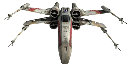
 During the creation of this model I mostly used the mirror tool to mirror the first wing of the ship into all 4 sections to quickly create the X wing model. This allowed for the basic shape and wing to be turned into a detailed model in considerably less time than when the TIE Fighter was being created.
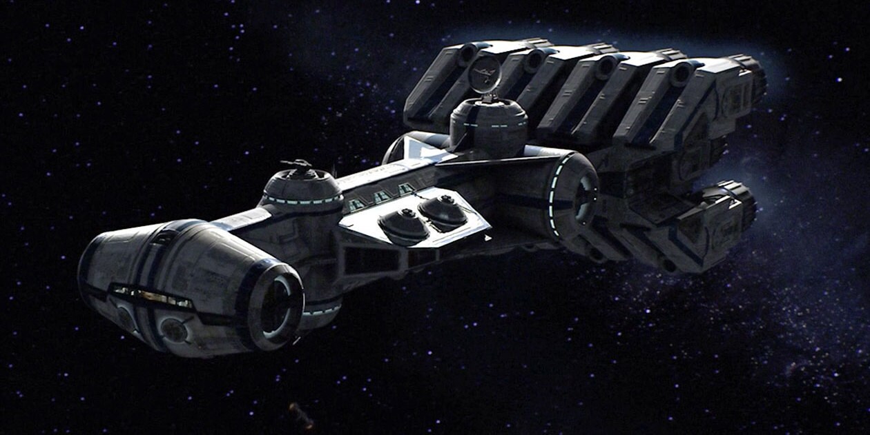
The model is accurate to the reference images used in the previous post, where sections where copied from each image to roughly form one details model.
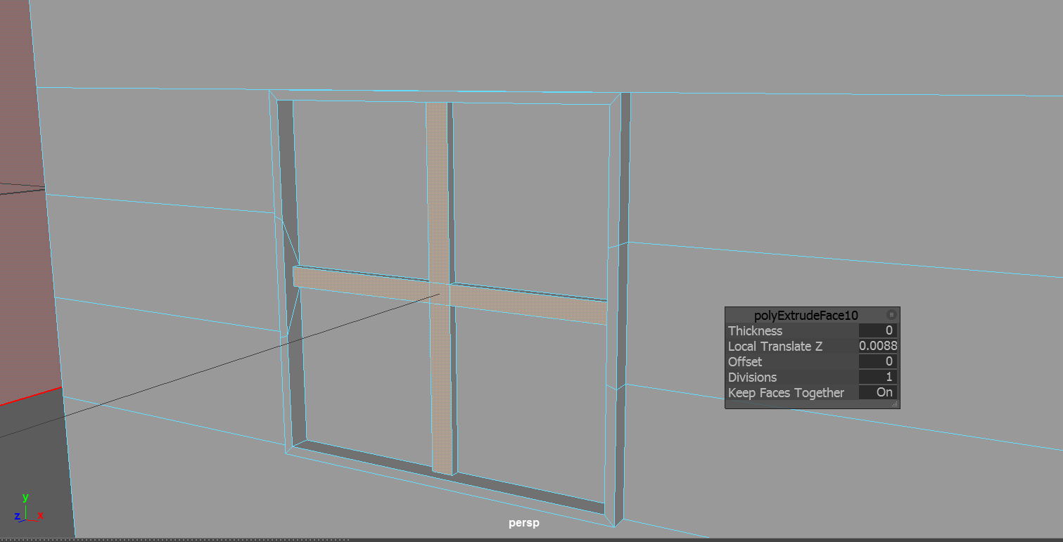
The nose of the ship is not as detailed as i would have liked however i decided that this could be added later on with a texture rather than adding in pipes and such in Maya.
I found it rather difficult to get the scale of the window correct as the angle of the window descending did not initially match the nose, however with some tweaking and editing this was made to fit correctly.
The wings and engine i would say look really good as they add a lot of detail and oomph to the ships look.

As i mentioned previously i had used a schematic to try and build the shape of the x wing, however i found it more difficult to make the shape fit to the schematic. I feel however that if i were to reference my current model against a schematic that i would closely fit to the shape of it.

X Wing (Part 1)

X Wing (Part 1)

Reference images:
1
2
3

Initially I had tried creating the X Wing using schematics that was added onto a plane in Maya and adjusted. However upon making the initial shape I realized that i found it harder to create the ship with it than i did when I used a reference image and modeled from that instead.
The main body of the ship is made using two shapes, one for the window housing and front of the ship, whilst the second used for the rear of the ship which houses the wings and engines.
The window section is then added over the top so that it can be lowered into place and worked on separately from the rest of the ship and added to the body later when needed.
 Each of the sections where made initially using a rough outline firstly to get the general shape of the ship before further pulling vertices and extruding the object. Vertices were connected to make the sections into one piece allowing for easier sculpting when adding more shape to the base of the ship.
 Each section was then manipulated to give it more shape against the reference images i used. I then added the nose cone so that the shape flowed along the reference more.
 The wing was firstly made using a re-scaled cube to form the base shape of the wing, with the front face scaled to add more shape to it. The engine is simple a cylinder which has been extruded on some of the faces to make it pop out as if there were moving exhaust pipes and such along the outside, the rear exhaust is made using another cylinder which is then extruded and scaled to form smaller sections before scaling inwards to form the cone exhaust at the rear.
I decided to make the wing more details initially as i knew that this section would be duplicated and mirror to create the X Wing shape and therefore would need the detail added earlier before being copied over.
Panel and other details were added by extruding in small areas where extra devisions were added only if i was planning on adding extra detail. This decision was made again to reduce poly count and to reduce rendering time in places where this level of detail was not needed and could have been given during the texture and materials phase of the model.

Wednesday, October 19, 2016

Making the TIE-fighter (Part 3)

TIE Fighter (Part 3)

The base model has been completed and in this section a go around the ship adding finer details where i deem necessary. During this I weighed the pro's and con's of adding finer detail as this increased the poly count exponentially. For panels and pipes it was decided to create the panel using a simple extrude and then texture the final details over the top.
 As shown below you can see two later pods below the ship. This was added as in my animation i plan on having a close up of the guns firing where this extra detail would be needed however instead of adding further details I will be adding it via textures and materials.
 The two reference images linked in the previous post i used to add finer detail where possible, in both images i could see a section that bulged out the back of the TIE Fighter and joining lines and panels at the top.
Shown above is the finished model of my TIE Fighter that i will be using in my final presentation.
I would determine that my model is close in accuracy to a TIE fighter that would be used in the star wars films, excluding unnecessary extra detail that will not be seem in my animation so I decided not to include it.

The wings could have been done better by making the wings out of one shape rather than building it using multiple shapes as this may have saved on the poly count by removing unseen sides and extras.

The Techniques i mainly used were Extruding, scaling, moving and resizing to create the basic shape of the model before i then created extra devisions to then add finer detail where it was needed. 
Initially I found it difficult to create the front window as I was not able to create the bezel around it as you can see in my first post. However learning from my mistakes I was able to more accurately create it the second time around.

The struts on the wings were the best looking section in my opinion as I like the way it is formed and shaped, making it look like it has come outwards of the body.

Monday, October 17, 2016

Making the TIE-Fighter (Part 2)

Making the TIE-Fighter (Part 2)

In my last post I talked about how i started my TIE fighter and the techniques used to create it up until the program crashed loosing my progress. 
In this section I used what I learned last time to quickly rebuild the initial model down from about 3 hours to roughly over an hour which for a first Maya model i would assume is very good.
Unlike the last time where i used the extrude tool to pull the frame out as is, this time i resized and created new devisions to allow me to create thinner frames and a rounder window on the TIE fighter as a whole.
I took a new approach in building the joining struts in which I pulled out the square section on the body with a cylinder shape attached and molded onto each side.

This was then mirrored to create both the side struts of the object. The reference image used here
I used the reference image to determine how long and how wide each strut should be as opposed to the body of the main ship.


Wings:

Each wing started out as a square where it was SLICED and then pulled outwards to create a hexagon shape which would be the base of the wing. Each strut across the wing is a separate object. First the base cylinder was added to the center of each side using the scale tool and extrude a smaller cylinder then protrudes outwards from it to create a center joining mechanism on it. 
Each strut is created using a single cuboid which is resized and pulled to create each strut, these are then positioned in the correct place before being resized and the corners bent to fit along the form of the hexagons base. 

The wing is then duplicated and copied to each side then scaled inwards to reduce the width, based on the reference images the wings are thinner than i initially made them, where i had to re-scale them to be thinner and more appropriately fitting with the model.
The wing is finally mirrored onto both sides and adjusted to give a reasonable gap between the wing and the base using the adjoining strut. This allowed me to make the distance bigger easily by simply increasing the length when needed against the reference image to make it look good.

Sunday, October 16, 2016

Making the TIE-Fighter (Part 1)


Maya: TIE - Fighter

Making the body

For the beginning of the body of the model i created a sphere which i would use as the base before then using tools such as extrude, scale and adding devisions to form the central window on the model.
Initially i had trouble forming the central window as I was unable to create the frame as seen in the reference photo. My method of creating it initially was to move the edges inside the window and extrude them out whilst scaling however this caused sections to unnecessarily overlap each other making the model look weird and not as it should.

After a while of testing different tools on multiple spheres to see its effects, I managed to create a smooth ring around the front to form the main frame, inside this i then added more devisions and extruded outwards to form the central frame and ring.

Cross section - Joining body and wings


Reference image: here

I used multiple web searches to compare various TIE fighters as each model was different, upon seeing this I decided to pick the best parts from various models to put together to create mine. 
To create the connections I selected faces on either side of the body before extruding and then moving the section outwards.

Stacked posts:

In the image below you can see how the joining section comes out from the main body then rotates inwards before coming directly outwards again. This was achieved by firstly extruding the shape outwards to where you can see the devision line, from here I would then use the extrude tools again to pull the section further before scaling it downwards so that the circle becomes smaller and the faces move inwards. At this point I then extrude again to bring the shape outwards in a straight line.


Upon completing the first section I then used the mirror tools to mirror the strut onto the opposite side which saved some time. Upon getting to this point I then decided to save my work at which point the program crashed on me, causing me to loose my work.


Wednesday, October 12, 2016

Making a house

Creating the house in Maya was simply created using a single cube with extra divisions added onto it.
For example below you can see the devisions that were added to allow for the ability to create the windows at the front of the house by pulling a middle face forward.
 To create the frames I added more divisions inside before then grabbing the edges and moving the closer together to create the frame you can see in the middle of the window, this was then extruded outwards to complete the window section.
 After working on the base shape of the house I decided to finish the practice of by adding a extension to the house, this was made again by adding more divisions and then pulling them outwards to create the slanted roof on top.
Most of Maya modelling I currently would say will be spent using the extrude tool on different shapes to pull and push them into creating lines and other shapes during this project.

Tuesday, October 11, 2016

Introduction: Mood & Story Board


Introduction


The module i am working on is 3D Modelling and Animation.

My overall task for this module is to produce 3 star wars ships and produce an exactly 30 second long animation involving these 3 models.

Weeks 1 - 7:
Design and prototype of 3 models
50% of Module

-Must blog the progress of the assignment.
-Create a mood board and a story board.


Mood Board:


The basic idea for my animation is a transport ship heading towards a planet that is attacked by a Tie Fighter, the transport ship is then saved by an X wing, who then guides the ship towards the planet.

I have chosen two out of the three required ships.
1: X Wing
2: Tie Fighter

The third ship i want to be a freighter or transport vessel, however i am unsure of which ship to choose at this time.


Storyboard:


The story I have decided will be split into 6 scenes, each scene will last approximately 5 seconds long. The scenes are as follows:


  1. The freighter and X-Wing are brought into view from an over the shoulder shot as they head towards the planet in the distance. 
  2. The Tie fighter moves into view travelling from right to left of the camera. The Tie fighter should then speed up to show that it has spotted the target.
  3. The camera then faces the Tie fighter as it fires towards the freighter and X-wing.
  4. X-Wing then pulls off the freighter and flies towards the Tie-Fighter, before opening fire with the camera hovering above looking down.
  5. The Tie-Fighter explodes and the camera then pan towards the freighter and X-wing
  6. The ships proceed to the planet at a closer range.